CONTENTS
Detailed description of the volume planner
Volume planner → Geometry menu
Add coordinate
Draw new geometry
Show geometry on map
Export GPX or KML
Delete geometry
Save geometry
Edit geometry
Parameters in the Assumptions section
Parameters in the UAS properties section
Adjust the parameter values
Reset parameters
Volume planner → Operational volumes
Pilot position / Set pilot position
Horizontal contingency volume SCV, Manoeuvre, SCM
Vertical contingency volume HCV, altitude HFG, Manoeuvre, HCM
Aim and purpose
The dipul volume planner is aimed at advanced users and supports them in defining/calculating the Operational volumes "Flight Geography", "Contingency Volume" and the "Ground Risk Buffer", which is mandatory for applying for an authorisation in the special category according to DVO (EU) 2019/947. Details can be found in the LBA guidelines.
The volume planner determines the required values for the Operational volumes based on your specifications and displays them two-dimensionally in the map tool.
In addition, the volume planner checks for overlaps between the flight area "Flight Geography" and the geographical zones "Geozones" defined in accordance with § 21h (3) LuftVO and lists them accordingly. The data obtained can be saved on your PC for further use, e.g. for applications to the LBA.
The instructions are intended purely to explain the range of functions and operation of the volume planner. The basic functions (e.g. location search, changing map layout) are explained in the Map Tool instructions. The instructions themselves do not provide an explanation of the LBA application procedure for the licence in the special category. Please read the relevant documentation, which can be found on the LBA website.
As with the Map Tool, the development of the volume planner focussed on a web interface that can largely be operated using the keyboard. All main elements can be focussed using the tab keys [Tab] or [Shift]+[Tab] in order to carry out further actions, e.g. entries. Further details can be found here.
Disclaimer
The generation of the correct Operational volumes "Flight Geography", "Contingency Volume" and the "Ground Risk Buffer", using the volume planner requires appropriate knowledge of the LBA guidelines. The volume planner supports you in determining these parameters. The volume planner does not replace the knowledge and understanding of the calculation according to the information in the LBA guidelines or the parameters to be used for the UAS used for the flight nor the verification of the results obtained by the user. All procedures and calculations are without guarantee of completeness. We assume no liability for damages of any kind resulting from the use of the volume planner. No legal claims can be derived from the use of the Volume Planner and the information obtained. The scope of the Volume Planner is limited to the Federal Republic of Germany.
Calling up the volume planner

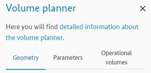
Use the stylised cube to open the Volume Planner tab, which contains the three menu items "Geometry", "Parameters" and "Operational volumes". To determine the correct operational volumes and the ground risk buffer, all three submenus must be checked and the corresponding entries made. The individual menu items can be activated using the mouse or keyboard. Please note that the appearance and the functionality offered by the menus may change during the course of your project as a result of the selected editing steps.
All parameters required for the calculation were pre-assigned with real, tested values in accordance with the LBA guidelines. On the one hand, this guarantees a realistic calculation and, on the other, rapid success in visualising the operational volumes and the ground risk buffer on the map. Please note that you must check the parameters and adapt them to your specific circumstances.
Quick guides
Create new project
- Volume planner → Geometry
- Determine planned flight area, e.g. via location search
- Select Type of geometry
- Create geometry, correct if necessary
- Save geometry
- Check/adjust UAS parameters. Under Volume planner → Parameters
- Check and adjust Assumptions for the parameters
- Adjust UAS properties according to the UAS intended for the flight
- Adjust/check operational volumes and ground risk buffer, check geographical areas (only possible if a geometry has been drawn in).
Under Volume planner → Operational volumes- Check/set parameters for the operational volumes (HCV, SCV) and Ground Risk Buffer
- Set pilot position
- Check for Geozones
- Save / export the required files to the PC for further use.
- You can export GPX or KML files under Volume planner → Geometry
- Export dipul files under Volume planner → Operational volumes
- Export geozones under Volume planner → Operational volumes
- You can export GPX or KML files under Volume planner → Geometry
Using an existing project
To use your own dipul file, you must have already exported an intermediate status or a finished project to a dipul file.
To use an existing dipul file, select Volume planner → Operational volumes → Import dipul file. Select your dipul file from your computer. After loading the file, your project is displayed in the volume planner and can be used according to your requirements. The steps for editing, checking the geometry or the parameters are analogous to the quick guide 'Create new project'.
Functions of the mouse buttons
In the different working modes, the left mouse button and the mouse cursor have a slightly different behaviour when the mouse cursor is positioned over the map.
Normal mode
The Volume planner tab is activated and "None" is selected in the "Type of geometry" input field in the "Geometry" menu. If the cursor is now moved over the map or is positioned over the map,
- the mouse cursor is displayed as a crosshair over the map.
- then a double-click on the left mouse button triggers a zoom effect on the map section shown. The map can also be zoomed in and out by using the mouse scroll wheel.
- the map can be moved by pressing and holding the left mouse button and moving the mouse in the desired direction.
Draw mode (for drawing geometry on the map):
After selecting a geometry type in the "Geometry" menu or after pressing the "Draw new geometry" button, you can easily draw a geometry on the map using the mouse.
If drawing mode is selected,
- there is a small blue circle under the crosshairs, which follows the crosshairs when you move the cursor over the map section.
- a geometry point can be placed on the map at the position of the mouse cursor by clicking (not holding) the left mouse button. A blue (auxiliary) line is created between the geometry point fixed on the map and the current cursor position, which subsequently connects the various geometry points and thus represents the shape of the geometry. For the "Circle" geometry, the edge of the circle is indicated by the blue line after the first geometry point (centre point) has been set.
- the map can be moved by pressing and holding the left mouse button and moving the mouse in the desired direction.
- Double-clicking the left mouse button when setting the last geometry point ends the direct drawing mode for the geometries and starts the editing mode. In the case of polygons, the geometry is closed. The double-click is not absolutely necessary for the circle geometry, as the radius of the circle is determined by setting the second point and the drawing mode is exited automatically. For polygons and corridors, additional geometry points can be added via the Geometry menu.
Editing mode (requires an existing geometry)
After completing the drawing, double-click (not required for circles) on the last geometry point or if the "Edit geometry" button has been selected,
- all set geometry points and the (auxiliary) lines of the geometry are displayed in blue.
- when hovering over one of the geometry points of the geometry with the mouse cursor, it is displayed in blue and can be moved to the desired position by pressing and holding while simultaneously moving the mouse.
- additional geometry points can be added to the geometry via the "Geometry" menu by pressing the "Add coordinate" button (not for circles).
Detailed description of the volume planner
Volume planner → Geometry menu
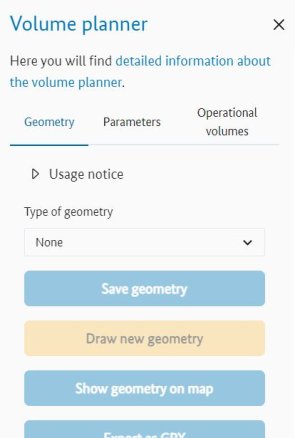
Depending on the current processing status of your project, the appearance and the functionality offered in the menu will vary.
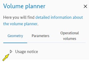
After initially calling up the volume planner (left mouse click on the tab with the stylised cube), the "Geometry" menu is activated, which is indicated by the light blue colour of the menu name and the light blue underlining of the menu name.
You can show or hide the "Usage notice" by clicking the triangle in front of the name "Usage notice". This applies to all buttons of this type.
No geometry should be available after the initial call-up of the volume planner, which is indicated by the fact that "None" is shown under the Geometry type input field and all buttons available in this menu are set to inactive.
Type of geometry
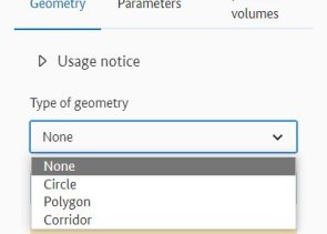
By default, 'None' is selected in the geometry type field, so you must first select a geometry type. To do this, click with the left mouse button in the input field under the designation "Type of geometry". The geometry types "Circle", "Polygon" and "Corridor" are available, which can be drawn and customised in terms of position, size and shape. By setting the geometry type, you activate the mode for creating a geometry.
Tip: Before you start creating a geometry, you should define the flight area on the map. This saves you having to move the map around in drawing mode. You can find out how to search for a location in the Map Tool help.
Please note that only one geometry with exactly one geometry type can be drawn at a time.
Draw geometry
Select the desired geometry in the "Type of geometry" input field. Place the mouse cursor directly on the map at the desired position where you want to set the first geometry point. Confirm the position by clicking the left mouse button. Release the left mouse button and drag the mouse cursor to the next position on the map where a geometry point is to be set and confirm this position by clicking the left mouse button.
For polygons and corridors, proceed as described above for each additional geometry point. Confirm the last geometry point by double-clicking the left mouse button. The volume planner switches to edit mode and displays the operational volumes (flight geography and contingency volume) together with the ground risk buffer on the map in accordance with the defined parameters. Additional geometry points can be added to the geometry using the "Add coordinate" button (not for circles).
By default, the width of the corridor is set to 400 metres. You can still adjust this according to your project in the "width" input field in the Geometry menu.
If you have selected "Circle" as the geometry type, it is not necessary to double-click to end the geometry. A circle is only defined by its centre point coordinates and its radius. With the first mouse click, the centre point of the circle is placed on the map, with the second mouse click you determine the radius of the circle, which then also closes the geometry and triggers the display of the geometry together with the contingency volume and ground risk buffer on the map.
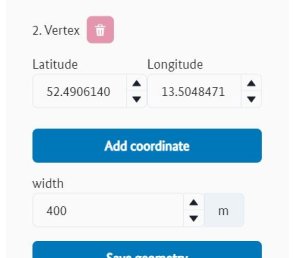
Add / delete coordinate
The "Add coordinate" button is only available for geometries of type "Polygon" or "Corridor". You may have to switch to edit mode to see the button. The editing mode can be called up via the "Edit geometry" button.
The geometry points "Vertex" are numbered consecutively and connected in series with lines. For a polygon, the last geometry point is also connected to the first geometry point. By clicking the left mouse button on the "Add coordinate" button, a further geometry point is added at the end of the series of numbers. The number of geometry points is thus increased by one. The newly added geometry point must then be adjusted with regard to its position on the map.
You can remove superfluous geometry points using the rubbish bin symbol behind the corresponding geometry point.

Draw new geometry
This point is ideal if you want to retain all existing settings and parameters from the "Parameters" and "Operational volumes" menus and simply create a new geometry. After pressing the "Draw new geometry" button,
- the existing geometry is deleted after confirmation in a pop-up window.
- the geometry type in the input field is retained.
- any parameters you may have customised in the "Parameters" and "Operational volumes" menus are retained.
- the mode for drawing a geometry directly onto the map is activated.
Show geometry on map

If your geometry has disappeared from the currently visible map area of the Map Tool during editing or only parts of the geometry are displayed in the visible map area, you can bring the map section with the complete geometry back into the visible working area of the Map Tool using the "Show geometry on map" button. The system scales the map accordingly so that the complete geometry is displayed in the visible area.
Export GPX or KML
These buttons allow you to save a file in the appropriate format for your current project on your computer, e.g. for further processing in another tool or for submission to your competent authority. Make sure that you send the correct file to your authority, that all the necessary settings in the "Parameters" and "Operational volumes" menus have been checked and set correctly and that the pilot position has also been entered accordingly ("Operational volumes" menu). Set the name of the file in the "Operational volumes" menu under the "Name" input field. The extension of the file corresponds to the format (.gpx or .kml) of the selected export. The file is saved in the download folder of your PC. If you have not assigned a name, the volume planner will use its own name. The volume planner generates an ID for this purpose.
Delete geometry

If you want to delete an existing geometry, you can do this using the "Delete geometry" button. After pressing the button,
- the existing geometry is deleted after confirmation in a pop-up window.
- any parameters you may have customised in the "Parameters" and "Operational volumes" menus are retained. Only the flight altitude HFG in the "Operational volume" tab is also reset, as it forms the operating volume with the geometry on the ground.
- the mode for drawing a geometry directly onto the map is activated.
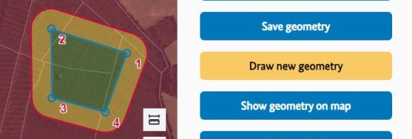
Save geometry
The "Save geometry" button simply ends the editing mode for creating a geometry, thereby preventing unintentional changes. You can recognise the active editing mode by the blue (auxiliary) lines of the drawn geometry and by the fact that the "Save geometry" button is displayed.
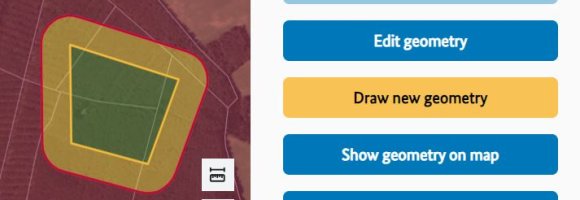
Pressing the "Save geometry" button changes the function of the button. The button is replaced by the "Edit geometry" function. In addition, the drawn geometry is displayed without (auxiliary) lines.
Saving the geometry does not protect against data loss. If you want to save your current work progress, please create a dipul file, which can be done in the "Operational volumes" menu using the "Export dipul file" button at the end of the menu.
Edit geometry
The "Edit geometry" button (previous image) takes you to edit mode. In this mode, you can edit the geometry via the side menu or directly on the map.
Changes in edit mode via the "Geometry" menu
- The input fields for the parameters describing the geometry (e.g. latitude and longitude) are enabled and can be changed. To do this, place the mouse cursor in the corresponding input field and enter the value. Alternatively, the value in the input field can also be changed using the triangles shown on the right-hand side of the input field.
- Additional geometry points can be added to the geometry using the "Add coordinate" button (not for the circle geometry type).
Changes in edit mode via the map
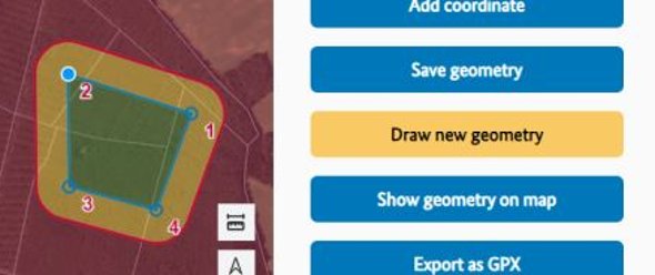
- In this mode, the (auxiliary) lines and geometry points (small circles) of the geometry are displayed in blue.
- If a geometry point is selected (see image) or the mouse pointer is positioned over it, it is displayed in blue and can be moved to the desired position by pressing and holding while moving the mouse.
- Additional geometry points can only be set using the "Add coordinate" button in the Geometry menu (not for circles).
Volume planner → Parameters
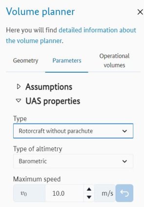
In the "Parameters" menu, you can edit the UAS-specific parameters "UAS properties" of the drone selected for the flight as well as the error tolerances made under "Assumptions", which have an influence on the calculation of the operating volume.
Click on the arrowhead in front of the name to open or close the corresponding section for further editing. At the bottom of the menu, you can reset all parameters in this menu to the default values using a button.
All parameters are preset for a realistic standard mission in accordance with the LBA guidelines. However, these values must be checked by you and adapted to the actual conditions. This applies in particular to the UAS characteristics.
Parameters in the Assumptions section
The following parameters can be found under the heading "Assumptions" and must be checked/maintained by you:
Parameter name in Map Tool | Symbol | Description |
GPS inaccuracy | SGPS | Deviation between measured and real position in meters |
Position holding error | SPos | Possible deviation when holding a position in stationary flight in meters |
Map error | SK | Inaccuracy of the map used for planning in meters |
Reaction time | tReak | Reaction time of the pilot in seconds |
Altitude error (barometric) | HBaro | Error in the height measurement by means of the used Baro sensor |
Altitude error (GPS) | HGPS | Error in the height measurement by means of the used GNSS module |
Additional distance (horizontal) | SAdd | Possibility to extend the horizontal contingency volume by an additional safety buffer in meters |
Additional distance (vertical) | HAdd | Possibility to extend the vertical contingency volume by an additional safety buffer in meters |
Parameters in the UAS properties section
Please note that the UAS properties and the calculation methods (formulas) depend on the drone type. Therefore, only the available and necessary parameters for the selected drone type are displayed in this section of the volume planner. The "Drone type" and "Height measurement" parameters shown in the following table are therefore not actual parameters. They define which parameters and formulas are used for the calculation and are included in the table for the sake of completeness.
The following parameters are available under the heading "UAS properties" and can be displayed and controlled/maintained by you depending on the drone type:
Properties / parameter name in the Map Tool | Symbol | Description |
Drone Type / Type | List of available types of drones | |
Opening time parachute | tSchirm | Time to open the rescue parachute in seconds |
Maximum speed during operation | v0 | Planned maximum speed during operation in meters per second |
Characteristic dimension | CD | Maximum UAS-size including propeller in meters |
Maximum permitted wind speed | vWind | Maximum wind speed during operation in meters per second |
Glide ratio | ε | Ratio of drag and aerodynamic lift, dimensionless |
Maximum roll angle | ΦUAS-max | Maximum rotation around the longitudinal axis of the UAS in degrees |
Descent rate with open parachute | vZ | Rate of descent with opened parachute in metres per second |
Velocity at stall | vStall | Stall speed in clean configuration (e.g. without useing flaps) in meters per second |
Maximum pitch angle | ΘUAS-max | Inclination around the transverse axis in degrees |
Height measurement |
| The type of height measurement depends on the sensor used |
Adjust the parameter values

The parameter input field is located under each parameter name in this menu. The input fields for "Type" and "Height measurement" are designed as drop-down menus. Numerical input fields are labelled with the corresponding formula symbol in accordance with the LBA guidelines for better orientation. Customise the parameters according to your circumstances. The switch at the end of the parameter input field resets the value to the default value.
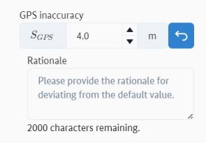
In the event of deviations from the default value, an input field opens below the entry "Rationale" in which you can enter your arguments for the deviation. The justification is saved in the dipul file, which can be made available to the relevant authority. The field allows you to enter 2000 characters. Depending on the length of the text entered, a scroll bar is displayed on the right-hand side of the input field, which you can use to scroll through the text. Alternatively, the size of the input field can also be adjusted using the hatched triangle in the bottom right-hand corner.
Please note: Changes to pre-assigned default values, which can have a negative impact on security, generate a warning. However, the calculation is still carried out. Values outside the valid value range generate an error, which must be corrected by adjusting the parameter.
Reset parameters

You can use the "Reset parameters" button at the end of the "Parameters" menu to reset all parameters in the Parameters menu to their default values at the same time.
Volume planner → Operational volumes
The menu offers a wide range of information, functions and other important setting options, which are grouped thematically under the corresponding name.
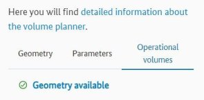
Geometry available / geometry missing
This note serves as a check and indicates whether a geometry is available for calculating the operational volumes. If the geometry is missing, create it in the "Geometry" menu. The designation is a link that takes you directly to the "Geometry" menu.
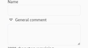
Name
Below this entry there is an input field in which you can enter a name for your project. The name is then also used to save your files on your computer. This is the only place where you can assign a name. There is no option to do this when saving the files.
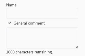
General comment
The triangle in front of "General comment" can be used to open or close the input field. To enter a comment, open the input field. The field allows you to enter 2000 characters. Depending on the length of the text you enter, a scroll bar will appear on the right-hand side of the input field, which you can use to scroll through the text. Alternatively, the size of the input field can also be adjusted using the hatched triangle in the bottom right-hand corner. The comment is saved in the dipul file, which can be made available to the relevant authority.
Pilot position / Set pilot position

Under the "Pilot position" entry is the "Set pilot position" button, which can be used to set the position of the pilot on the map (as required in the guide). If the "Set pilot position" button is pressed, a submenu with coordinate input fields (latitude and longitude) for the position and three further buttons ("Save", "Show pilot position on map", "Delete pilot position") is displayed. In addition, the pilot position (red location marker) is placed in the centre of the visible working area on the map.
Change pilot position
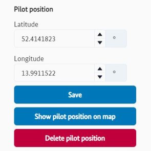
You can use the fields shown in the menu (Latitude and Longitude) to change the position of the pilot according to your specifications. Save the position using the corresponding button to exit edit mode.
Alternatively, the position of the pilot can also be plotted directly on the map. To do this, move the mouse cursor to the desired position on the map. Confirm the position of the pilot by clicking the left mouse button. This saves the position and exits edit mode.
Save
The "Save" button ends the editing mode and the position currently displayed on the map or in the coordinates is fixed as the pilot position. It is only necessary to press the button if the pilot position was set via the coordinate input fields in the menu. After saving, the button changes its function to "Set new pilot position". This function does not protect against data loss. If you want to save your work, create a dipul file.
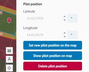
Set new pilot position on map
You can use the "Set new pilot position on the map" button (only available after saving) to overwrite the current pilot position or set a new pilot position.
Show pilot position on map
Switch "Show pilot position on map". If the pilot position is not in the current view area of the map tool, you can use this button to jump to the pilot position.
Delete pilot position
The "Delete pilot position" button removes the current pilot position and closes the "Set pilot position" submenu.
Horizontal contingency volume SCV, Manoeuvre, SCM
In the "Horizontal contingency volume" section, the values calculated on the basis of your entries (parameters controlled or selected by you) are displayed. You can also enter your own value for the horizontal contingency manoeuvre.
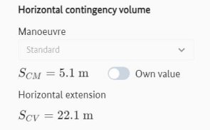
- Manoeuvre: In the "Manoeuvre" input field, select the contingency manoeuvre that is to be performed for this flight when leaving the flight geography in a horizontal direction. The manoeuvre depends on the drone type selected in the "Parameters" menu. If the field is inactive, no further manoeuvres are available and the standard manoeuvre must be performed.
- SCM: SCM stands for the minimum horizontal distance to execute the contingency manoeuvre in metres. The specified value was calculated by the system according to the parameters. You have the option of entering your own value for SCM, which is used for the calculation.
- Horizontal extension (SCV): The "Horizontal extension" entry contains the value for the horizontal extent of the contingency volume in metres calculated by the system according to the selected parameters, which is displayed in the various graphics.
Set your own value for SCM
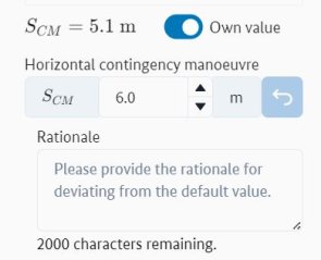
To do this, activate the "Own value" button. By activating the switch, two additional input fields are displayed below the field in which you can make the corresponding entries.
- Horizontal contingency manoeuvre SCM: The input field in which you can adjust the value according to your requirements is located under this designation.
- Rationale: If you have selected your own value for the horizontal contingency manoeuvre, you must insert a justification for the approving authority here.
Vertical contingency volume HCV, Altitude HFG, Manoeuvre, HCM
This section provides the values for the "Vertical contingency volume" calculated on the basis of your entries (parameters controlled or selected by you). You also have the option of setting your own values for the altitude of the flight area and for the vertical contingency manoeuvre.
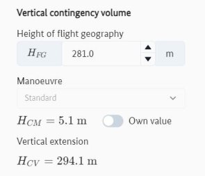
- Height of flight geometry HFG: The input field for the planned flight altitude is located under "Height of flight geometry". The value can be entered/changed there directly using the keyboard or alternatively increased or decreased using the two buttons with the triangles at the end of the number field.
- Manoeuvre: In the "Manoeuvre" input field, select the contingency manoeuvre to be performed for this flight when leaving the geometry in a vertical direction. The manoeuvre depends on the drone type selected in the "Parameters" menu. If the field is inactive, no further manoeuvres are available and the standard manoeuvre must be performed.
- HCM: HCM stands for the minimum vertical distance for executing the contingency manoeuvre in metres. The specified value was calculated by the system according to the parameters. You have the option of entering your own value for HCM, which is used for the calculation.
- Vertical extension (HCV): The "Vertical extension" entry contains the value calculated by the system for the vertical extent of the contingency volume in metres, which is displayed accordingly in the various graphics.
Set your own value for HCM
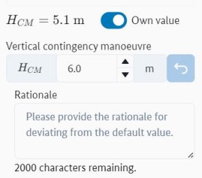
To do this, activate the "Own value" button. By activating the switch, two additional input fields are displayed below the field in which you can make the corresponding entries.
- Vertical contingency manoeuvre HCM: The input field in which you can adjust the value according to your requirements is located under this designation.
- Rationale: If you have selected your own value for the vertical contingency manoeuvre, you must insert a justification for the approving authority here.
Ground Risk Buffer SGRB, Manoeuvre
Under this entry, the manoeuvre that influences the ground risk buffer (according to the LBA guidelines) can be set in the selection field. The ground risk buffer is significantly influenced by the altitude of your flight area and manoeuvre.
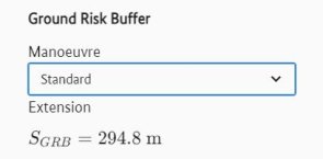
- Manoeuvre: In this input field, you determine the procedure for scheduling the flight.
- SGRB: Value for the ground risk buffer calculated by the volume planner according to your specifications (horizontal extent of the ground risk buffer in metres).
Operational volumes
This section contains the calculation method for determining the operational volumes (Flight Geography + Contingency Volume) and the Ground Risk Buffers, as well as their schematic representation in horizontal and vertical dimensions.
Calculation method
Under the heading "Calculation method", you will find the drop-down menu for defining the calculation method. The "From inside" method is selected by default. Both methods described in the LBA guidelines are available:

Calculation method "From inside": The size of the flight geography results directly from the geometry drawn in. The contingency volume and the ground risk buffer are added.
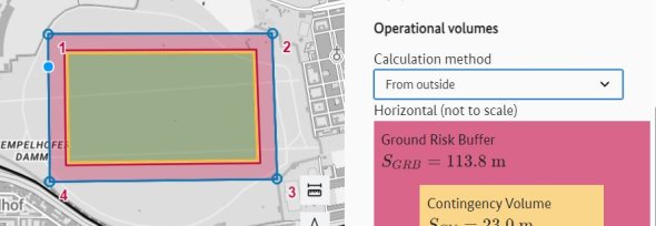
Calculation method "From outside": The geometry drawn in the Map Tool corresponds to the total area of Flight Geography plus Contingency Volume plus Ground Risk Buffer. The size of the flight Geography therefore results from the size of the geometry drawn minus the contingency volume minus the ground risk buffer. This means that the drawn geometry must have a certain size so that the flight geography, the contingency volume and the risk buffer can be displayed correctly.

If the size of the geometry you have drawn is not sufficient, the volume planner displays a message box for 10 seconds and the geometry is displayed without contingency volume and ground risk buffer.
Schematic representation of the operational volumes
Following the calculation method, you will find the schematic, not to scale, illustrations of the relevant values in analogy to the LBA guidelines Kapitel 5.3.
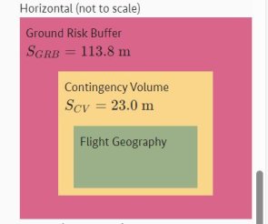
In horizontal orientation (top view):
- To the Flight Geography with the value for SFG (only for circle).
- To the Contingency Volume with the calculated value for SCV
- To the Ground Risk Buffer with the calculated value for SGRB
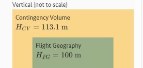
In vertical orientation (side view):
- To the Flight Geography with the value for HFG.
- The Contingency Volume with the calculated value for HCV.
Geozones
Under this point, the flight geography is checked for overlaps with any existing geozones.
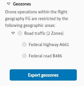
Check overlap with geographical areas
Clicking on the triangle in front of the "Geozones" label starts / interrupts the validation and listing of the results. Depending on the size of the flight geography and the number of affected geographic areas , the validation may take some time. A rotating circle is displayed during the validation. Once the check is complete, the result is displayed in list form and categorised by area. The triangle in front of the area name takes you to the list of individual geographic areas of the same type. By clicking on the name of the relevant geographic area, you can call up its details.
Export geozones
You can use the "Export geozones" button to save the result of the check as a csv file for further use on your PC. The file extension is .csv. The file is saved in the download folder of your PC. If you have not assigned a "Name", the volume planner will use its own name. The volume planner generates an ID for this purpose.
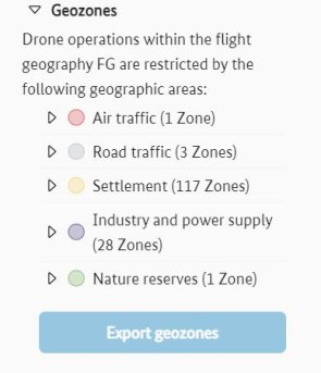
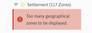
The list of affected geographic areas of the same category is limited to a number of 100 entries (number of zones). If the number of affected geographic areas exceeds this value within an category, a warning is displayed in the listing. The warning becomes visible when you open the corresponding geographic area via the triangle in front of the area name. In this case, it is not possible to export the data to the corresponding file, which is also signalled by the inactive "Export geozones" button.
In the example shown, the check for overlaps between the flight geography and the geographic areas resulted in a number of 117 zones of the category "Settlement". It is therefore no longer possible to list the individual geographic areas of this type and an export of all geographic areas found is suppressed.
Export dipul file and Import dipul file buttons
The "Export dipul file" button can be used to save the current project on your PC for further use. The volume planner saves the project (drawn geometry, parameters and comments as entered by you) according to the current work progress. The system uses the name entered in the "Name" input field for saving. The file extension is .dipul. The file is saved in the download folder of your PC. If you have not assigned a name, the volume planner will use its own name. The volume planner generates an ID for this purpose.
You can use the "Import dipul file" button to import one of your created dipul files at any time in order to reuse it in the volume planner.
Export as DOCX file

Use this button to create a detailed description of your flying site in .docx format. You can insert the information obtained with this export (image and description of the flying site) into the operating licence required by the LBA under the chapter "Flying sites". After pressing the corresponding button, the volume planner saves the document in the download folder of your PC. If you have not assigned a "name", the volume planner uses its own name, for which an ID is generated.
The export of the .docx file cannot be carried out with the satellite background maps.
